Electronics Forum
Electronics Circuits & Projects discussion forum. Get help with electronics.
On/off regulator voltage change
Moderator: pebe
2 posts
• Page 1 of 1
On/off regulator voltage change
![]() by Mavrik » Thu Aug 04, 2011 5:44 pm
by Mavrik » Thu Aug 04, 2011 5:44 pm
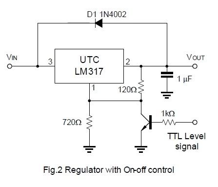
In the below circuit, at about 1 volt at the TTL, it turns off the output. How do I change this so it turns off very close to the regulated output? Which will be 12V. I tried changing the 1K resistor and it didn't change the results. Yes, the circuit shows for a 8.75V output, I changed it to 12V
- Mavrik
- Posts: 4
- Joined: Thu Aug 04, 2011 5:22 pm
Re: On/off regulator voltage change
![]() by JMACgyver » Thu Aug 11, 2011 11:22 pm
by JMACgyver » Thu Aug 11, 2011 11:22 pm
================
MAVRIK doth spoke:
In the below circuit, at about 1 volt at the TTL, it turns off the output. How do I change this so it turns off very close to the regulated output? Which will be 12V. I tried changing the 1K resistor and it didn't change the results. Yes, the circuit shows for a 8.75V output, I changed it to 12V
================
Hence the reply:
A question:
Do you mean you want the circuit to turn off around say, 10 volts, rather than 1 volt? If so, TTL input to the circuit is not what you need. TTL voltages are 5v or 0v. most circuits will interpret anything below 2.2v as zero, and anything at let's say, 3v or higher (up to 5v) as 5v.
However, feeding back part of the comparator output to the switch might be useful. If you can follow the current flow, you might want to try changing which type of transistor you're using, (maybe try a PNP) or altering the other two resistors in the lower part of the diagram.
Personally, I would look at circuits for voltage-controlled switches, and then incorporate one of those into the regulator circuit. From there, I find it easiest to experiment with trial-and-error component swapping. Messy, i know, but I learn better that way. A data sheet on the LM317 might help you figure out where to tweak.
I know this isnt a solution, but I hope it helps get you to one.
--Electro--
aka David M.
~~~~~~~~~~~~
"In Theory, there is no difference between practice and theory. In Practice, there is."
~~~~~~~~~~~~
- JMACgyver
- Posts: 46
- Joined: Mon May 09, 2011 7:23 pm
- Location: Texas
2 posts
• Page 1 of 1
Return to Electronic Circuits Help
Who is online
Users browsing this forum: No registered users and 12 guests
 |
Powered by phpBB® Forum Software © phpBB Group