
 On eBay Now...
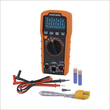
Digital Multimeter DT830D Mini LCD Display Digital Multimeter Voltmeter Ammet... For Sale

When you click on links to various merchants on this site and make a purchase, this can result in this site earning a commission. Affiliate programs and affiliations include, but are not limited to, the eBay Partner Network.

Digital Multimeter DT830D Mini LCD Display Digital Multimeter Voltmeter Ammet...:
$12.95
DT830B LCD Digital Multimeter Ammeter AC DC Voltmeter Mini Handheld Digital Multimeter Cable Ohm Meter with Probe CombinationDescription• LCD screen: The digital multimeter has an LCD screen that makes it easy to read and interpret the measurements.• AC/DC Voltage Measurement: This multimeter can measure AC and DC voltage, making it versatile and useful for a variety of applications.• Combination Probe: The combination probe allows for easy and accurate measurement of resistance, capacitance and inductance, making it a valuable tool for electronics enthusiasts and professionals.• Mini for you: The compact size of this multimeter makes it easy to carry and store, making it perfect for on-the-Go use or for those with limited work space.Product advantages: It is suitable for users who have a preliminary understanding of the multimeter to help DIYProduct technical characteristics:DC voltage: 200-2000-20-200-500V ±0.5%AC Voltage: 200-500V ±1.0%DC current: 200u-2000u-20m-200m-5A ±1.8%Resistance: 200-2000-20K-200K-2000K ±1.0% ±1.0%.General product characteristics:LCD screen sizeLow voltage symbol display: YesOverload protection: YesDiode detection: Yes, showing approximate voltage dropTriode detection: YesPower supply: 6F22 9V battery (without battery)Product size: 125x70x25mmStandard configuration: Stripping meter, color box, pen, manual, certificate of conformity (warranty card)Panel and operating instructions:1. MonitorThree and a half digit LCD display2. SwitchPress it to turn on the power and turn off when not in use.3. Capacitance measurement socketThis watch does not have capacitance test function.4. Function range switchChoose from different measurement functions and ranges.5. 10A current jack (cannot measure current greater than 10A)When measuring AC and DC currents greater than 200mA and less than 10A, the red test lead should be inserted into this 10A current connector.6. Current JackWhen measuring AC and DC currents less than 200mA, the red test lead should be inserted into this current connector.7.V/Ω JackWhen measuring AC and DC voltage, resistance, diode driving voltage and short circuit detection, the red test lead should be inserted into this V/Ω connector.8. The black test lead from the common grounding \"COM\" Jack end is always inserted into this grounding Jack.9. β value test socketInsert the collector, base and emitter of the triode under test into the \"C\", \"B\" and \"E\" jacks respectively, and pay attention to distinguish whether the triode is NPN or PNP.Instructions:1. PreparePress the power switch, observe whether the LCD screen is normal and whether there is a sign of battery shortage, if so, please replace the battery first.2. Use(1) Direct current measurement Select the appropriate current measurement range and insertion hole of the red test lead according to the size of the measurement current. When measuring DC, the red test lead touches the end with high voltage, the black test lead contacts the end with low voltage, and direct current flows from the red test lead. Flow into the multimeter, and then flow out of the black test lead. When the magnitude of the current to be measured is not clear, first use the largest range to measure, and then gradually reduce the range to measure accurately.(2) AC and DC voltage measurementInsert the red test lead into the \"V/Ω\" connector, select the appropriate voltage measurement range according to the voltage, the black test lead touches the \"ground\" end of the circuit, and the red test lead touches the point to measure in the circuit. In particular, it should be noted that the frequency of the AC voltage measured by the digital multimeter is very low (45 ~ 500Hz), and the voltage amplitude of the medium and high frequency signal should be measured with an AC millivolt meter.3) Resistance measurementInsert the red test lead into the \"V/Ω\" connector, select the appropriate Resistance Measurement range according to the size of the resistor, touch the red and black test leads at both ends of the resistor and observe the reading. In particular, when measuring in-circuit resistance (resistance on the circuit board), the circuit power supply should be turned off first, so as not to cause reading fluctuations. It is prohibited to use resistance equipment to measure current or voltage (especially AC 220V voltage), otherwise it is easy to damage the multimeter. In addition, the resistor file can also be used to qualitatively judge whether the capacitor is good or bad. First short circuit the two poles of the capacitor (use a test lead to touch both poles at the same time to discharge the capacitor), then touch the two test leads of the multimeter to the two poles of the capacitor respectively, and observe the resistance reading displayed . If the resistance reading displayed at the beginning is very small (equivalent to a short circuit), then the capacitor begins to charge, the resistance reading displayed gradually increases, and finally the resistance reading displayed becomes \"1\" (equivalent to an open circuit), Then the capacitor is OK If the above steps are followed and the displayed resistance reading remains unchanged, then the capacitor is damaged (open circuit or short circuit). Special attention should be paid to selecting the appropriate resistance range according to the size of the capacitance when measuring, for example, 200K range for 47μF, 2M range for 4.7μF, etc.(4) Diode Conduction Volting DetectionIn this gear, the red test lead is connected to the positive power supply inside the multimeter, and the black test lead is connected to the negative power supply inside the multimeter. The connection between the two test leads and the diode is shown in Figure 1. If measured according to the connection method in Figure 1(a), the diode under test is conducting forward, and the multimeter shows the forward conduction voltage of the diode in mV. Generally, the forward conduction voltage of a good mV silicon diode should be 500 to 800mV, and the forward conduction voltage of a good germanium diode should be 200mV to 300mV. If \"000\" is displayed, it means that the diode is short-circuited, and if \"1\" is displayed, it means that the diode is not forward. If measured according to the connection method in Figure 1(b), it should display \"1\", indicating that the diode is reverse cut-off. If it displays \"000\" or other values, it indicates that the diode has reversed decay. This file can also be used to judge the quality of the triode and identify the pins. When measuring, first connect one test lead to a designated PIN, and connect the other test lead to the other two pins successively. Change two test leads and test again. If they are not on or both are on twice, it can be confirmed that the triode is good, and it can be confirmed that the identified PIN is the base of the triode. If the red test leads are connected to the base and the black test leads are respectively connected to the other two poles, it means the triode is NPN type, otherwise it is PNP type. Finally, compare the forward conduction voltage of the two PN junctions. The largest reading is the be junction, and the smallest reading is the BC junction, so the collector and emitter are identified.(5) β test of transistor valueFirst of all, it is necessary to determine whether the triode to be tested is NPN type or PNP type, then insert its pins into the corresponding type of test socket correctly, and turn the function range switch to the β position, i.e. , the β value can be read directly from the display screen. \"000\", means the triode is broken.Suggestion:1. Pay attention to the correct selection of the range and test of Red Lead Jack. When measuring an unknown quantity, first adjust the range to the maximum and then adjust from large to small until suitable. If \"1\" is displayed, it means overcut, and the range should be increasedWhen not measuring, the power should be turned off at any time.When changing the range, the test lead must be disconnected from the measured point.When measuring current, avoid overload.5. It is not allowed to measure voltage with resistance file and current fileWarning:Due to the different monitor and light effect, the actual color of the item may be slightly different from the color shown on the pictures. Thank you!Please allow 1-2cm measuring deviation due to manual measurement.DetailsDC current200u-2000u-20m-200m-5A ±1.8%DC Voltage200m-2000m-20-200-500V ±0.5%AC voltage200-500V ±1.0%Measurable resistance range200-2000-20K-200K-2000KΩ ±1.0%Dimensions125*70*25mmCraft SuppliesELECTRICALOriginCN(Origin)

Digital Multimeter Voltmeter Ammeter AC DC Volt Ohmmeter Tester Meter Auto Range
$9.95
Klein Tools #MM420 Digital Multimeter, Auto-Ranging TRMS Multimeter.
$46.55
Automatic Anti-Burn Intelligent Auto Digital Multimeter DC/AC Voltage Resistance
$19.69
![]()
Popular Tutorials
Alarms and Indicator Circuit diagrams- Power supply failure alarm
- Theft preventer alarm
- Rain Alarm
- A simple electronic buzzer
- Water Level Indicator with alarm
- Stereo Channel Selector
- Low cost intercom using transistors
- Infrared Head Phones
- Use the CD-ROM drive as a audio CD player without the computer
- Audio Visual Indicator for Telephones
- Ultrasonic pest repellent
- Charge Monitor for 12V lead acid battery.
- Wiper Speed Control
- Dome Light Dimmer for Cars
- Car anti theft wireless alarm.
- Control electrical appliances using PC
- Simple Analog to Digital Converter
- PC based Frequency Meter
- 7 segment rolling display using PC
- Electronic Scoring Game
- JAM(Just A Minute) Circuit
- Flashy Christmas Lights
- TV remote control blocker
- Light Flasher (blinking lights)
- Automatic Dual output Display
- Emergency Light
- Automatic Room Lights
- Running Message Display
- Automatic Speed Controller for fans & Coolers
- Soft Button type Motor Direction Controller
- Super simple stepper motor controller
- Discrete component motor direction controller
- Negative supply from single positive supply
- Self switching Power Supply
- Ultra low drop linear voltage regulator
- Car anti theft wireless alarm.
- Long range FM transmitter
- Remote control using VHF modules
- 40 meter Direct Conversion Receiver
- Remote control using VHF modules
- Remote control using telephone
- A simple Remote control Tester
- Clap Activated Remote
- Radio Remote Control using DTMF
- Ultrasonic switch
- Magnetic proximity sensors
- Dew sensor
- Color Sensor
- Metal Detector
- Optical toggle switch using a single Chip
- Telephone Ringer using 556 dual timers
- Two line intercom plus a telephone changeover switch
- Telephone line based audio muting and light on circuit
- Having secrecy in parallel telephones
- Telephone call meter using calculator & COB
- High Resistance Voltmeter
- A simple Remote control Tester
- Contactless Mains Voltage Indicator
- Zener Diode Tester