
 On eBay Now...
4-Channel MOSFET Driver Board 5-24V DC Switch Module Arduino ESP32 | KI Maker For Sale
When you click on links to various merchants on this site and make a purchase, this can result in this site earning a commission. Affiliate programs and affiliations include, but are not limited to, the eBay Partner Network.

4-Channel MOSFET Driver Board 5-24V DC Switch Module Arduino ESP32 | KI Maker:
$19.95
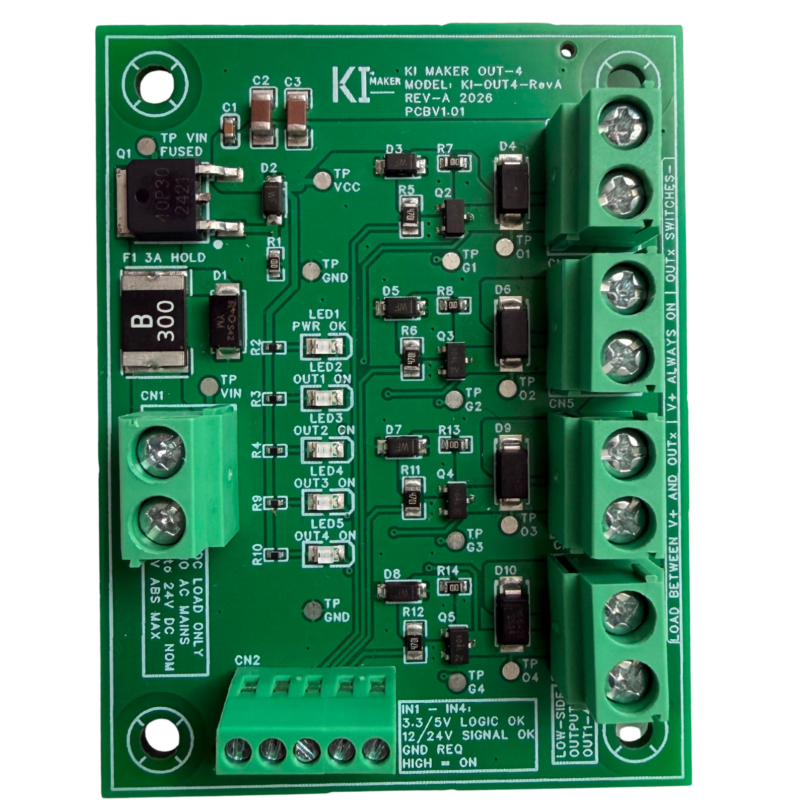
KI Maker OUT-4
4-channel MOSFET DC driver and switch module for Arduino, ESP32, STM32, Raspberry Pi GPIO and similar 3.3V / 5V controllers
Switch four real-world DC loads from one controller without building four separate MOSFET driver circuits. Connect an external 5–24V DC load supply and use four independent logic inputs to control fans, LED loads, relay coils, solenoids, small pumps, indicators and other compatible low-voltage DC loads. One board for four controller-driven DC outputsThe KI Maker OUT-4 is a compact four-channel low-side MOSFET output board designed for projects where a microcontroller or control board needs to switch loads that should not be driven directly from a GPIO pin.
OUT-4 combines four MOSFET-switched outputs, screw terminals, a protected DC power input, per-channel flyback diodes, gate-protection circuitry, status LEDs and troubleshooting test points on one clearly labeled PCB.
It is suitable for custom automation projects, robotics, CNC accessories, test fixtures, equipment enclosures, maker projects and prototype control systems when operated within the published electrical limits.
Key features- 4 independent low-side N-channel MOSFET switched outputs
- 5–24V DC nominal load supply
- 30V DC absolute maximum input
- 3.3V and 5V logic-compatible control inputs
- HIGH input turns the corresponding output ON
- Up to 1.0A continuous per channel
- 3.0A maximum total board current
- Resettable PPTC input fuse
- Input TVS surge suppression
- Per-channel Schottky flyback diodes for common inductive DC loads
- MOSFET gate resistors, pull-downs and zener gate clamps
- PWR OK and individual output status LEDs
- Labeled troubleshooting test points
- Compact 65 × 50 mm PCB
- Four M3 mounting holes
LOW = corresponding output OFF. Per-channel current Up to 1.0A continuous per channel within published operating and thermal limits. Total board current 3.0A maximum total board current. Input protection Resettable PPTC fuse, reverse-polarity protection and TVS surge suppression. Inductive-load support Per-channel Schottky flyback diodes for common low-voltage inductive DC loads. Output isolation Non-isolated low-side MOSFET outputs. Controller ground must be connected to CN2 GND. Short-circuit protection Individual output channels are not short-circuit protected. Typical applications
- DC fans
- LED lighting and indicators
- Relay coils
- Small DC pumps
- Buzzers and indicators
- CNC accessories
- Robotics and prototype automation
- Maker and microcontroller projects
Compatible control signals include common 3.3V and 5V logic used by Arduino-compatible boards, ESP32 modules, Raspberry Pi GPIO projects, STM32 development boards and similar controllers.
How the outputs workOUT-4 uses low-side MOSFET switching. The load is connected between the positive supply rail and the selected OUT terminal.
Connection Connect to Load positive V+ Load negative Corresponding OUT1 / OUT2 / OUT3 / OUT4 terminal Controller signal Corresponding IN1 / IN2 / IN3 / IN4 terminal Controller ground CN2 GNDWhen INx goes HIGH, the corresponding MOSFET switches OUTx toward ground and turns the connected load ON.
Important wiring note:Do not connect the load between OUTx and GND. The OUT terminals are switched MOSFET outputs and are not isolated relay contacts. Connector reference Connector Function CN1 Load power input: DC+ / DC- CN2 Controller interface: IN1 / IN2 / IN3 / IN4 / GND CN3–CN6 Paired V+ and OUTx load connections for each output channel Status indication & troubleshooting
OUT-4 includes onboard indicators and test points to make setup and troubleshooting easier:
- PWR OK LED
- OUT1 / OUT2 / OUT3 / OUT4 status LEDs
- VIN test point
- VCC test point
- GND test point
- Gate test points
- Output test points
These provide convenient measurement locations during setup and troubleshooting with a multimeter or oscilloscope.
Important operating limits- Low-voltage DC only. Do not connect AC mains anywhere on the board.
- Observe correct DC input polarity.
- Do not exceed 30V DC input.
- Use only within the published current and thermal limits.
- OUT1–OUT4 are non-isolated low-side MOSFET switches, not relay contacts.
- The individual output channels are not short-circuit protected.
- Do not short an output terminal to ground or supply.
- Incorrect output wiring or a short circuit can permanently damage an output channel.
- Controller ground must be connected to CN2 GND for valid logic signaling.
- Always verify that load voltage, current, inductance, switching frequency, duty cycle and stored energy are appropriate for the board.
- Mount the PCB on insulated standoffs and protect it from conductive debris.
- Verify load current and board temperature during initial operation.
- Provide appropriate airflow when operating near maximum loading or inside an enclosure.
This product is intended for indoor low-voltage electronics, maker projects, prototypes and control applications. It is not intended for AC mains switching, medical equipment, life-safety systems, automotive safety functions, emergency-stop systems or fail-safe applications.
Mechanical PCB size 65.00 × 50.00 mm Mounting pattern 55.00 × 40.00 mm Mounting holes 4 × Ø3.20 mm M3 clearance holes What’s included- 1 × KI Maker OUT-4 assembled MOSFET output board
- Model: KI-OUT4-RevA
- Revision: Rev-A
- PCB Version: V1.01
Not included: External power supply, controller, loads, wiring, mounting hardware or accessories.
Designed and documented by KI Maker
The OUT-4 is supplied as an assembled, clearly labeled output-driver board with published electrical and operating limits. Its integrated status indicators, protection circuitry and accessible test points are designed to make controller-driven DC load projects cleaner to wire and easier to troubleshoot than assembling multiple separate generic switching modules.
Hilitand 4-Channel MOSFET PWM 3-20V to 3.7-27VDC 10A Driver Module PLC Amplifier
$15.89
4-Channel MOSFET Driver Board 5-24V DC Switch Module Arduino ESP32 | KI Maker
$19.95
4 Channel MOSFET Trigger Switch Module 10A 400W PWM Control Board DC 3.7–27V
$17.49

Popular Tutorials
Alarms and Indicator Circuit diagrams- Power supply failure alarm
- Theft preventer alarm
- Rain Alarm
- A simple electronic buzzer
- Water Level Indicator with alarm
- Stereo Channel Selector
- Low cost intercom using transistors
- Infrared Head Phones
- Use the CD-ROM drive as a audio CD player without the computer
- Audio Visual Indicator for Telephones
- Ultrasonic pest repellent
- Charge Monitor for 12V lead acid battery.
- Wiper Speed Control
- Dome Light Dimmer for Cars
- Car anti theft wireless alarm.
- Control electrical appliances using PC
- Simple Analog to Digital Converter
- PC based Frequency Meter
- 7 segment rolling display using PC
- Electronic Scoring Game
- JAM(Just A Minute) Circuit
- Flashy Christmas Lights
- TV remote control blocker
- Light Flasher (blinking lights)
- Automatic Dual output Display
- Emergency Light
- Automatic Room Lights
- Running Message Display
- Automatic Speed Controller for fans & Coolers
- Soft Button type Motor Direction Controller
- Super simple stepper motor controller
- Discrete component motor direction controller
- Negative supply from single positive supply
- Self switching Power Supply
- Ultra low drop linear voltage regulator
- Car anti theft wireless alarm.
- Long range FM transmitter
- Remote control using VHF modules
- 40 meter Direct Conversion Receiver
- Remote control using VHF modules
- Remote control using telephone
- A simple Remote control Tester
- Clap Activated Remote
- Radio Remote Control using DTMF
- Ultrasonic switch
- Magnetic proximity sensors
- Dew sensor
- Color Sensor
- Metal Detector
- Optical toggle switch using a single Chip
- Telephone Ringer using 556 dual timers
- Two line intercom plus a telephone changeover switch
- Telephone line based audio muting and light on circuit
- Having secrecy in parallel telephones
- Telephone call meter using calculator & COB
- High Resistance Voltmeter
- A simple Remote control Tester
- Contactless Mains Voltage Indicator
- Zener Diode Tester